
This project is inspired by Ben Eater’s VGA display project, where the goal is to build a circuit that generates the correct timing of sync signals for a VGA monitor to display an image stored on an EEPROM. While Ben Eater’s version displays a single 100×75 pixel image with a 64-color palette, my version introduces significant upgrades. These include support for two images that can be controlled both asynchronously and synchronously, and an increase in color depth from 64 colors to 256 colors. This is achieved by fully utilizing the 8 bits of the AT28C256 EEPROM instead of the 6 bits used in the original version.
Upgrading the project to support two images required only minor adjustments, as the full address space of the AT28C256 EEPROM was not used in the original project. The EEPROM has 15 address pins (A0-A14), but in the original video, the most significant address pin, A14, was left unused. By utilizing this pin, the EEPROM was effectively divided in half, with each half storing a separate image. Controlling which image is displayed is simple: toggling the A14 signal between logic 0 and logic 1 selects one of the two images. This toggle can be controlled automatically using a fixed timing mechanism or manually by the user.

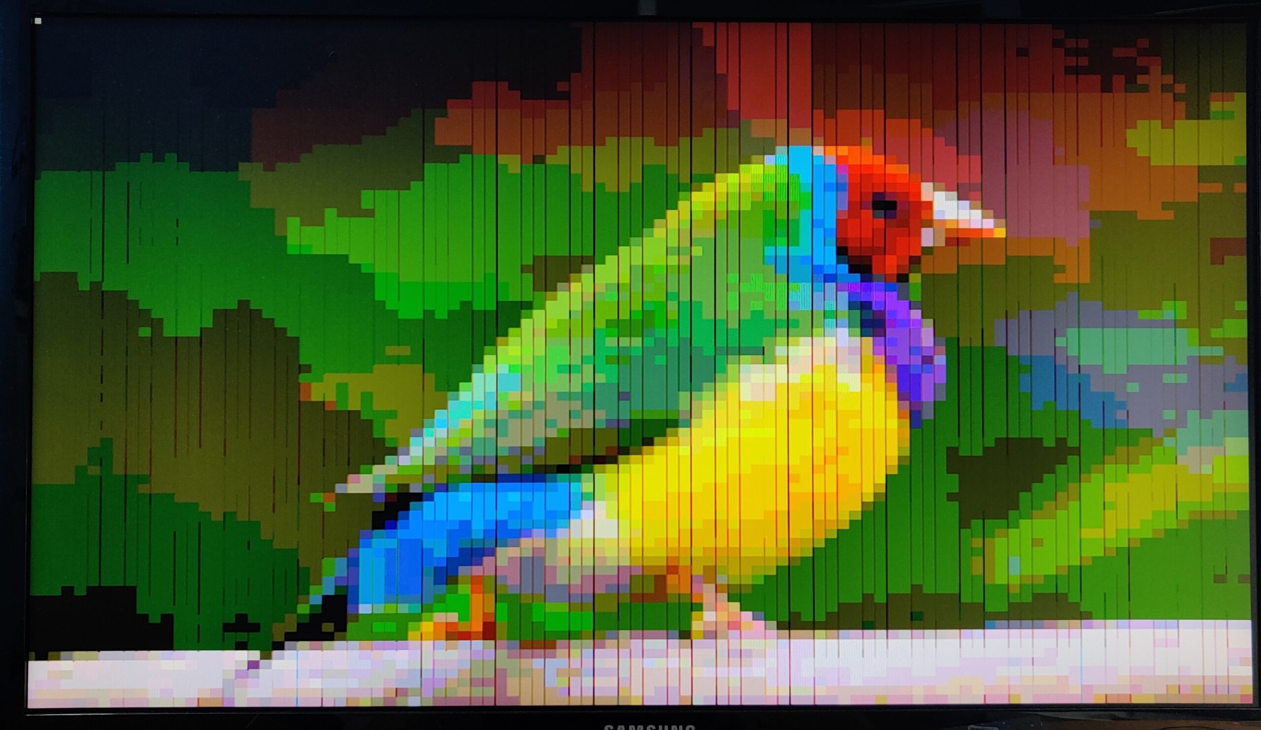
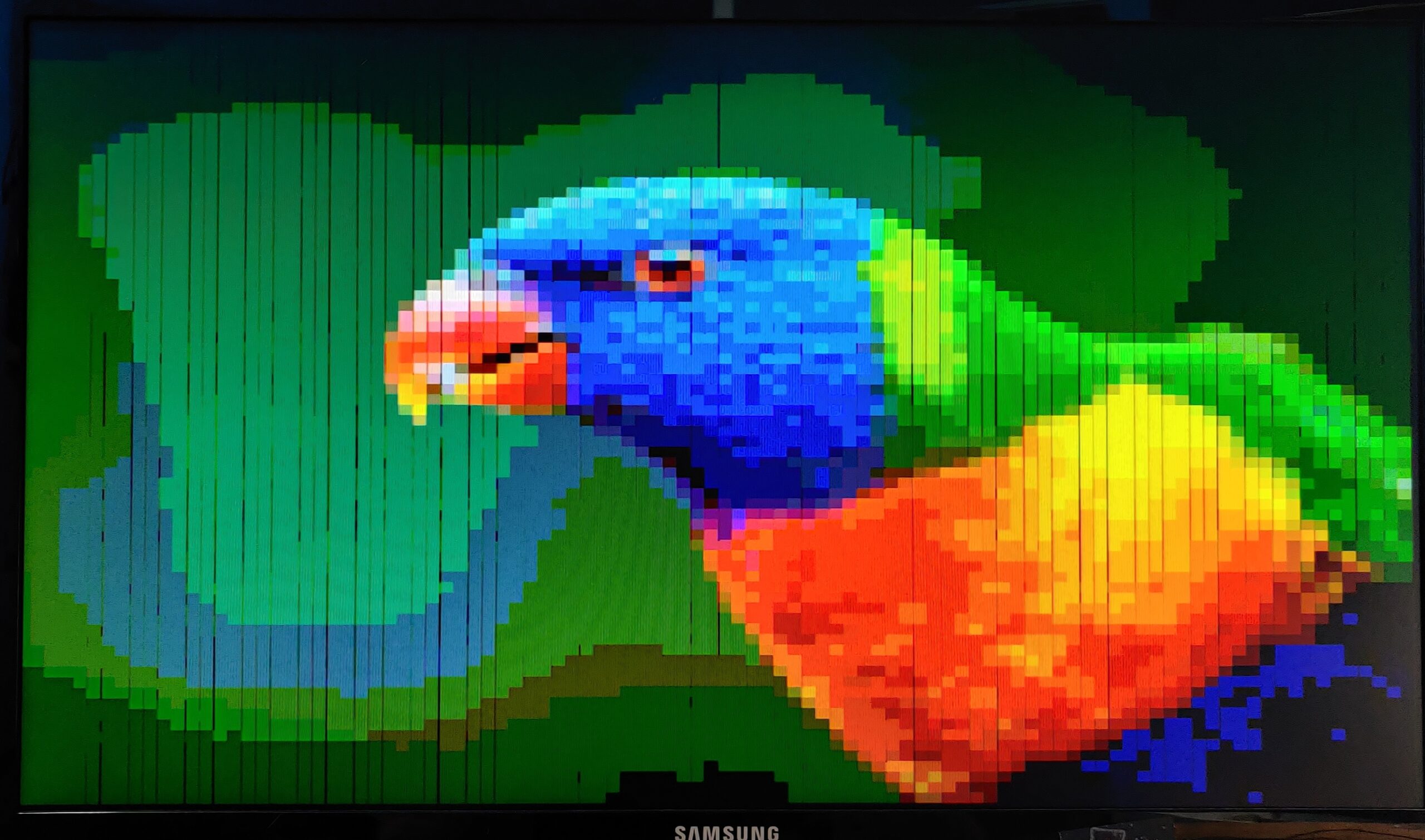
Here are photos showing the result of the Finch and Bird images displayed on the VGA monitor. These photos demonstrate how the images look after being processed and stored on the EEPROM.


The control mechanism for switching between images offers three modes, selected via sliding switches: astable, monostable, and bistable. In the astable mode, the image changes at regular intervals using an adjustable clock built with a 555 timer chip and a potentiometer to vary the frequency. The monostable mode uses a set resistor and capacitor value to switch images based on a fixed timing. Finally, the bistable mode allows the user to manually change the displayed image by pressing a button that toggles between the two states.
Ben Eater’s original project used 6 bits for color, allowing for a palette of 64 colors. Two bits were used for each of the three color channels: red, green, and blue. However, since the EEPROM has 8 bits, I expanded the color palette to 256 colors (2^8 = 256) by using all available bits. The 8 bits are organized as follows:
- The least significant 3 bits (bits 0-2) represent the red channel.
- The next 3 bits (bits 3-5) represent the green channel.
- The most significant 2 bits (bits 6-7) represent the blue channel.
This expanded palette allows for greater color depth while maintaining the same method of generating the required voltage levels via voltage dividers. These dividers divide the voltage signal into two or three equal parts, depending on the channel.
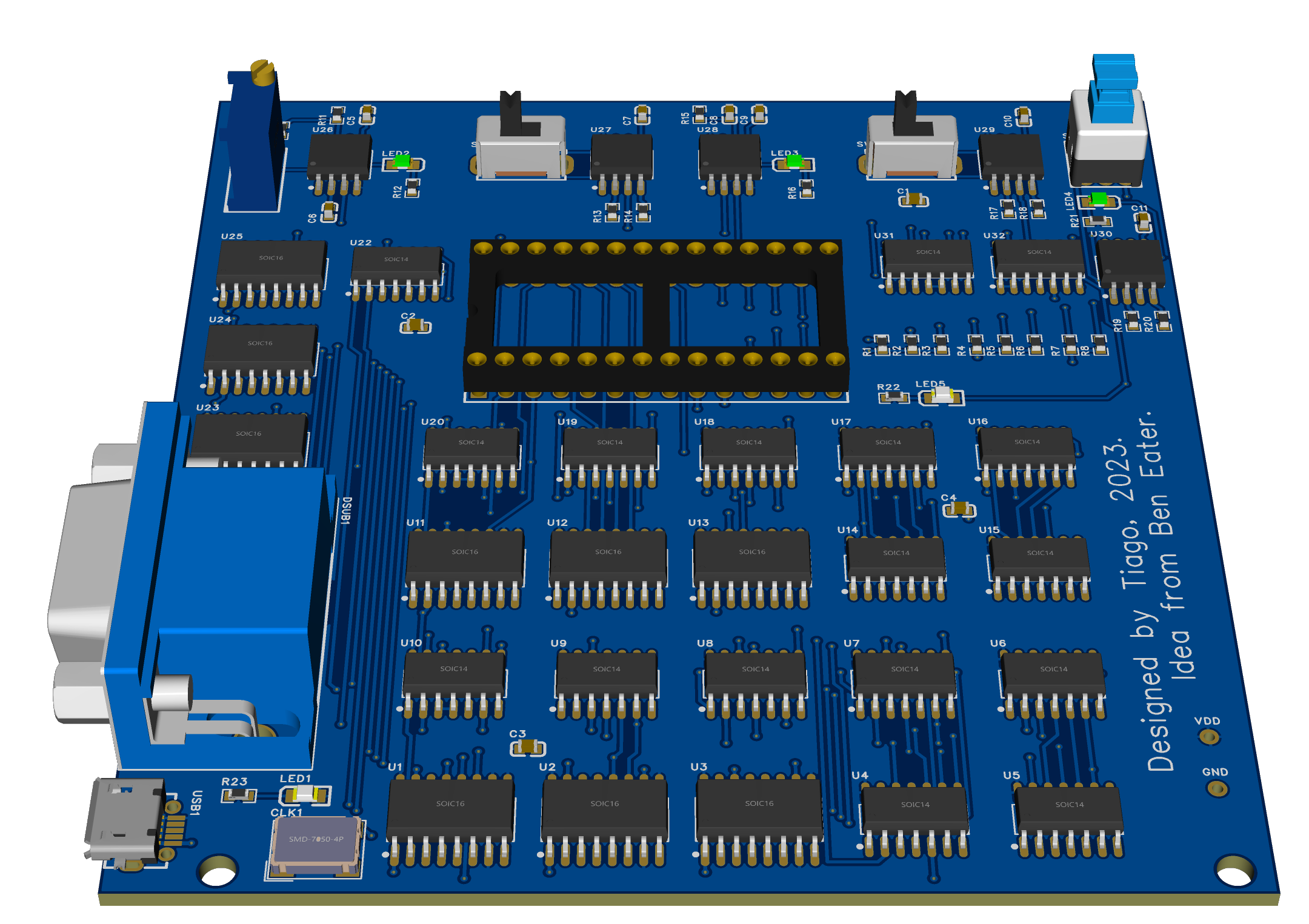
The project was initially prototyped on a breadboard to test the circuit. After the design was confirmed to be working, I transitioned to designing and printing a custom PCB using an online service. This made the circuit more reliable and compact compared to the breadboard version.


In Ben Eater’s video, Photoshop was used to convert images to the defined 64-color palette, and Python was then used to convert the image to a .bin file, which was uploaded to the EEPROM using a programmer. Since I did not have access to Photoshop or an EEPROM programmer, I created a Python script to convert each pixel of a 100×75 image to one of the 256 possible values, and then used an Arduino Mega to upload the image to the EEPROM. The Arduino Mega was chosen due to its higher memory capacity, allowing one image to be saved and loaded into the EEPROM at a time. This process has some limitations: the Mega only has enough memory to handle one image at a time, and it takes approximately 1 minute and 20 seconds to program a single image.
There are several future enhancements planned for this project:
- Increasing Resolution: A higher resolution image could be displayed, but this would require faster hardware and a more efficient EEPROM to handle the increased data.
- Improved Circuit Design: Adding bypass capacitors as close as possible to each component on the PCB will help mitigate noise and improve signal integrity.
- Better EEPROM Quality: Purchasing EEPROM chips from reputable sources may help reduce screen artifacts and improve the quality of the displayed image.
- Improved Color Conversion Algorithm: The current algorithm used to convert pixel colors to a 256-color palette is relatively simple, based on dividing the color range into equal parts. A more sophisticated algorithm could be developed to better map image colors to the 256-color space, optimizing the visual output. This would help take fuller advantage of the available color palette.
- Faster EEPROM Programming: The speed of EEPROM programming could be improved by using Port Manipulation on the Arduino. This method involves manipulating the microcontroller’s port registers directly, allowing for faster and more efficient control of the I/O pins compared to the higher-level
digitalWrite()functions.
 https://github.com/CandeiasV2/VGA-EEPROM-Image-Display
Leave a Reply